18.08.2019

Turbo Chargers 2 Stepp Install Driagram

Turbo Chargers 2 Stepp Install Driagram Average ratng: 4,5/5 491 reviews
  1. V8 Single Turbo Diagram
  2. How To Install A Twin Turbo
  3. Twin Turbo Installation Diagram

Car turbo kits are widely available, and many people can install one in their car if they. The two main parts of a turbocharger are the turbine and the compressor. With the proper equipment, and careful study of the step-by-step instructions,.

Performance‎ > ‎Engine‎ > ‎LD9 2.4L Twin Cam‎ > ‎Forced Induction‎ > ‎Turbocharging‎ > ‎

How-To: Install a Turbocharger Setup

This task is not for those who are not mechanically inclined. The process is relatively straightforward, but can be a pain at times. It will take longer than you think. This guide is designed for non cruise-control equipped engines.

Contents

  1. 2 Install Injectors - Part 1
  2. 4 Install Gasket/Modify PCV
  3. 5 Install Injectors - Part 2
  4. 10 Modify Coolant Bleed Hose
  5. 11 Remove the Exhaust Manifold
  6. 12 Oil Pan Modification
  7. 13 Install Turbo Manifold
  8. 14 Prepare Turbocharger
  9. 16 Install Oil Lines
  10. 17 Install Intercooler

Tools/Parts Required

  • deep-well and regular sockets
  • open ended and box wrenches
  • ratcheting wrenches
  • allen wrenches
  • welding capabilities
  • drill with drilling bits
  • hose clamps (four 5/8' and at least four 1/4')
  • 1/4' brass hose barb fitting to thread in
  • 4 feet of 5/8' ID high pressure washer hose (thick wall)
  • 10 feet of 1/4' ID fuel hose (thick wall)
  • automotive vacuum check valve
  • automotive 2 way vacuum check valve (not required, but suggested)
  • 1/4' NPT plumbing adapter for oil feed line
  • teflon tape

Install Injectors - Part 1

Relieve System Pressure

To make sure you don't get a pressurized splash of fuel when removing the fuel rail and injectors from the engine, pull the Fuel Pump relay from the under hood fuse box. Attempt to start the vehicle. If it runs, let it die. Crank the engine over for 3 seconds when it won't start. The fuel rail should now have no pressure.

Remove Fuel Rail

The fuel rail is held in by two bolts that go into the head. Disconnect the wiring harnesses going to the camshaft tower and each fuel injector. Disconnect the vacuum hose that runs to the fuel pressure regulator. To remove the injector connections from the injectors, use needle nose pliers to grab the light blue piece and pull it up from the injector. It will move out about 1/2' and stop. Now you will be able to depress the black tab on the center of the injector wire connector and pull the connector upwards and off the injector. Do this for all four.
Remove the two bolts that hold the fuel rail in. The fuel rail should now be able to pull up and off the cylinder head. Try to hold all of the injectors in the rail when pulling the assembly out of the head in order to avoid any unplanned fuel spillage.

Remove Throttle Body

Disconnect all intake piping and couplers from your air intake. Unplug the two sensors on the throttle body, and disconnect the vacuum hoses from the throttle body.
Pry up the two plastic pushpins that hold the throttle cable cover down to the throttle cable bracket. Remove the cover to gain access to the throttle cable assembly. Rotate the throttle to wide-open and slide out the throttle cable's end through the hole. Now the cable is disconnected from the throttle body and can be moved aside.
Unbolt the throttle body from the intake manifold by removing the four 10mm bolts. Remove the throttle cable cover and the throttle body and set aside.

Install Gasket/Modify PCV

We must take a break from fuel system modification and do what needs to be done with the intake manifold, since the fuel rail normally would be somewhat in the way of unbolting the manifold.

Remove Intake Manifold

Unplug the MAP sensor's electrical connection (only sensor on the intake manifold). Unbolt the 7 bolts (5 top, 2 bottom) holding the intake manifold to the head. Remove the manifold and set aside.

Remove/Modify PCV Baffle

The plastic piece with two hose connections underneath the intake manifold that is bolted to the engine block is the PCV baffle. Disconnect the hoses from it, and unscrew the bolts that hold it on. Remove the PCV baffle. Drill a small hole on the right-top side of the baffle, just large enough to allow you to force thread in a 1/4' brass hose barb fitting in. You can tap this if you want and use teflon tape, but just forcefully screwing it in has worked so far for me.

Reinstall PCV Baffle

Put the baffle back on and bolt it to the engine block. Connect some vacuum hose to the brass barb fitting, enough to reach the throttle body. Place a check valve inline, allowing air to only flow OUT of the PCV baffle, and blocking all pressurized air IN.

Reinstall Intake Manifold

Place the new flat intake manifold gasket (that blocks off the small hole between ports 2 and 3) between the intake manifold and the cylinder head. Line it up, and thread in the bolts. Tighten the intake manifold to the head.

Install Injectors - Part 2

Remove Injectors

Be sure to have a few absorbent towels underneath the fuel rail when removing the injectors. There will be fuel. The injectors just pull out.

Install Injectors

Slide a coating of clean engine oil on the o-rings before pushing the injectors into the fuel rail. This will help seal them and allow you to get them in without distorting the o-ring.

Reinstall Fuel Rail

Coat the o-rings with clean engine oil. Push the fuel rail into place by aligning the injectors with the holes in the cylinder head and pressing the rail so they fit into the holes. Install the two fuel rail bolts you removed. You may now connect the wiring harness to the injectors and the camshaft position sensor.

Install MAP Sensor

To install the new MAP sensor, remove the vacuum hose that runs from the center front of the intake manifold to the MAP sensor, and simply slide the old sensor off of where it mounts on the intake manifold, and put the new one on and connect it with some new vacuum hose. Reconnect the MAP sensor's electrical connection.

Reinstall Throttle Body

Bolt the throttle body back down to the intake manifold by reinstalling the four bolts. Be sure to place the throttle cable bracket in between the bolts and the throttle body.
Reconnect the electrical connections to the TPS and IAC on the throttle body. Leave all vacuum lines disconnected for now.

Modify Brake Booster

The hard metal brake booster hose gets in the way of things. Disconnect the rubber hose behind the engine that runs to it (and where it connects to the brake booster), and remove the hardware (nuts/bolts) that hold it to the engine. Remove the brake booster hose. You may have to bend it quite a bit to remove it, but it is not important, as it will be replaced.
Once you work the metal hose out of the engine bay, discard it. Cut the 5/8' high pressure hose to size and connect it to the throttle body's large barb fitting and to the brake booster's barb fitting using hose clamps. This allows it to run alongside the engine all the way instead of coming up behind the engine and getting in the way of the turbocharger.
(New brake booster hose, center, clamped to the bottom of the brake booster assembly)

Drain Fluids

Drain the oil and coolant. Open the oil and coolant caps. Then unscrew the oil pan drain bolt and collect the oil that drains out. Remove the oil filter and collect the oil that drains from that. To drain the coolant, it gets messier. Pull off the metal hose that runs under the oil pan and is clamped on by a rubber hose. A significant amount of fluid will drain from this location. The rest will pour out during another step.

Modify Coolant Bleed Hose

The stock coolant bleed hose is a metal tube that runs from the driver's side of the engine (coming out of the large plastic coolant outlet) and runs behind the engine. A rubber hose connects from that metal hose to the coolant overflow reservoir. This coolant line will get in the way of the turbocharger, so we must route it in front of the engine instead.

Cut Hose

Cut the metal line just past the bracket that holds it in place next to the plastic water outlet. Leave enough room to slide a 1/4' fuel hose over the end. Discard the rubber and metal stock hoses.

Add Hose

Connect a 1/4' ID fuel hose to the cut section, clamp it. Route the hose to the coolant reservoir in the same spot you disconnected the old hose, but this time have the hose routed over the intake manifold instead of behind the engine like the stock metal one was. Clamp everything tight.

Remove the Exhaust Manifold

Remove Dipstick

Remove the one nut that holds the dipstick bracket in place (rear of engine, on the camshaft cover). Pull the dipstick up and out of the engine block.

Disconnect Stock Downpipe

Use an electric saw to cut the downpipe just before it makes the bend to horizontal piping, or as far back as you have new exhaust pipe to fit.

Disconnect O2 Sensor

Unplug and unscrew the stock upstream oxygen sensor that is in the exhaust manifold and save for later.

Remove Manifold

Remove the bolts that hold the heat shield in place, discard both. Remove the nuts on each stud that hold the exhaust manifold in place against the cylinder head. Then slide off the exhaust manifold. Discard.

Oil Pan Modification

In order to use an oil drain line, the oil pan must be modified to accept an AN braided hose fitting. Mark a spot (as high as possible) on the rear of the oil pan, to the right of the black metal coolant hose that runs down behind the oil pan and under it. Leave enough room to weld on all sides of the fitting you intend to put into the hole.

Remove Metal Coolant Hose

The metal hose you disconnected from the rubber under the oil pan and drained part of the coolant from must be removed in order to be able to remove the oil pan. It elbows and runs up to the water pump area behind the engine. There are two bolts or nuts you can access from the top with a socket extension. Unscrew and remove them, and then pull the metal line from the bottom off and out of the engine bay. There will likely be a significant amount of coolant that will drain out. Prepare for a shower. I suggest a parka and goggles.

Remove Oil Pan

Remove the many various bolts that hold the oil pan onto the bottom of the engine block and to the transmission. There is a lot of them. Once they are all off, you should be able to drop down the oil pan off the engine and out through the subframe. It might require some wiggling to find the right angle that it all fits through at, but it does come out. Do not damage the oil pan gasket (it may even stick to the bottom of the block and not fall out).

Drill Hole

Drill a hole where you marked so that there is enough room for the 1/2' NPT x -10AN 90 degree fitting to fit beside the coolant line and enough room for you to thread on a braided hose and AN fitting to it. If the fitting is anodized, be sure to grind off all of the coating on the threads before welding.

Clean

Clean the oil pan completely so that welding will not be hazardous and will not be poorly done with a dirty surface.

Weld

Insert the 90 degree fitting's thread side into the oil pan hole you just drilled, leaving it sticking out far enough so that you can twist on an AN fitting to the -10AN side of the 90 degree fitting once the oil pan is reinstalled.

Reinstall Oil Pan

Place the oil pan back onto the engine block, being sure to line up the gasket. Reinstall all of the bolts you removed and tighten securely.

Reinstall Metal Coolant Hose

You may now reinstall the metal coolant hose elbow using the two bolts or nuts that you removed from it. Reconnect the metal hose to the rubber one under the oil pan using a new hose clamp instead of the stock rusted squeeze clamps.

Install Turbo Manifold

Install Wastegate [Blockoff Flange]

If you have an internal wastegate, install the block off flange/plate to the bottom of the manifold using the wastegate flange, bolts and lock washers.
If you are using an external wastegate, bolt it to the bottom of the manifold with the supplied hardware and use a wastegate gasket.

Install Manifold

Slide the manifold in place onto the header studs. Put the nuts back on and tighten.

Wastegate Tube

If you are using an external wastegate, you must either route a pipe straight down, or route it to the downpipe (difficult). For now, just dump it straight down using a pipe and flange angled similarly to the one in the image.
Later, one can add piping to splice the dump tube into the rest of the exhaust system at any local exhaust shop with ease.

Prepare Turbocharger

Clock Housings

Clocking the housings is another way of saying rotating each side of the turbocharger to the orientation desired/required to install on the vehicle. The bolts on the CHRA are designed to be loosened, and then the housings are able to rotate about the center axis to whichever direction you want the inlet/outlet of the turbine/compressor, respectively. If the turbocharger has been used, the turbine side may require some negotiation (rubber mallet). A vice is also handy for this operation.

Oil Lines

Secure the oil drain line flange to the bottom of the turbocharger's center hub rotating assembly (CHRA) using the supplied bolts and lock washers. If the gasket you were supplied came from eBay, and is not a metal type, do NOT use it. Purchase a roll of Fel-Pro oil-use gasket material and cut your own gasket. The eBay one will disintegrate and leak.
Secure the oil feed flange to the top of the turbochargers CHRA in the same way. Be sure that the oil feed line or flange has a restrictor built into it (very small orifice, not a hole the size of the hose).
Do not connect any oil feed or drain AN fittings or braided lines yet.

Install Turbocharger

Once the housings are rotated the way they need to be, and your oil feed and drain connections are accounted for, place the turbocharger onto the manifold and secure it with four bolts and lock washers, being sure to use a gasket between the turbo and the manifold to prevent leaks.
The turbocharger can be seated with the turbine side on either the driver or passenger side of the manifold mounting point, depending on how you rotate it. For ease of downpipe fabrication, having the turbine side on the passenger side is suggested.

Install Oil Lines

Oil Feed Line

Remove the stock oil pressure sensor by disconnecting the electrical connection (cable tie it out of the way somewhere if desired, it's going to stay disconnected forever), and then unscrewing it from its position in between the camshaft towers.
Thread the 1/4' NPT adapter into the camshaft tower using teflon tape, and then thread in the oil feed line into the adapter, also using teflon tape. Tighten.
Connect the oil feed line to the turbocharger oil feed flange on the top of the CHRA. No tape necessary, the connection seals via the flare angle.

Oil Drain Line

Install a straight AN fitting to one end of your braided stainless steel hose, and thread the fitting onto the turbocharger's oil drain flange on the bottom of the CHRA.
Route the hose down to where the fitting is in the oil pan. You're going to be using the 45 degree fitting on the oil pan fitting, not a straight AN fitting. Observe the length of the braided hose. Remove the fitting from the CHRA in order to cut the hose to length. Leave enough wiggle room so you don't cut it too short.
Fit the 45 degree AN swivel fitting onto the just cut end of the braided hose, and then install the hose to the CHRA and the oil pan 90 degree welded fitting.

Install Intercooler

Remove Front Bumper

The front bumper, if stock, is typically attached with 3 bolts on either side under the fender, two pushpins under the hood at the front top center of the bumper, and various other plastic pushpins along the bottom and fenderwell (the plastic liners need to be disconnected from the bumper.

Remove Plastic Bumper Support

The bumper support is held on by two U bolts on either side of the support. You can remove these by unscrewing the nuts on each and hammering the main plastic bumper support piece away from the actual metal support. This gives us enough room to mount the intercooler.

Attach Intercooler

The intercooler should come with some basic hardware, such as bolts that fit in the intercooler's threads, and metal brackets. Or you can fabricate your own brackets. Just a piece of metal with two holes in it, bent at a 90 degree angle.
You may use self-tapping screws to attach the brackets to the metal front bumper support once centered and aligned where you want it. Put a bolt through each bracket and thread it into the top of the intercooler core's threaded bungs to attach.

Install Blow Off Valve

Connect your 90 degree silicone coupler to the throttle body using clamps (t-bolts, ideally), and depending on what you've purchased (blow off valve pipe or simply the blow off valve flange), you'll either clamp on or weld.
If you have a BOV pipe adapter, which is a short section of pipe with a blow off valve flange welded to it already, simply insert one end into the 90 degree silicone coupler off the throttle body and clamp it down at an angle that will clear the hood. If you have a BOV flange, piece together a charge pipe to fit over the battery and bend down into the fenderwell where the stock plastic intake system used to be. Cut a hole in the pipe where the BOV is to be mounted, and weld the flange to the pipe.
Install the BOV using the supplied gasket and bolts.

Connect Vacuum/Boost Hoses

Connect a hose from the blow off valve's barb fitting to the throttle body at any of the small ports.
Connect the PCV hose (that has the check valve in it coming from the PCV baffle under the intake manifold) to the throttle body at a small port.
Connect the HVAC hose (gray plastic with rubber elbow) and the EVAP canister hose (comes from the bottom left of engine bay near the serpentine belt) to a two way check valve, ideally, and the check valve to the larger port on the throttle body.
The fuel pressure regulator (FPR) hose can be connected to the other open small port on the throttle body. You can splice your boost gauge hose into this hose using a plastic T fitting.

Fabricate Charge Piping

The intercooler/charge piping runs from the turbocharger to the intercooler to the throttle body.
Using mandrel bent aluminum piping, cut sections to size to route the piping as such. Connect your 90 degree silicone coupler to the turbocharger that adapts the turbo outlet to the charge piping size (commonly 2' to 2.5'). Piece together the aluminum piping, weld as many connections as feasible, and use high quality 4-ply silicone couplers and t-bolt clamps on those you are unable to weld.
Weld the aluminum 3/8' bung into the charge pipes as close as possible to the throttle body, and thread in the new IAT sensor and connect it electrically.

Reinstall Front Bumper

Once your charge pipes are installed and tightened, you can reinstall your front bumper.

Downpipe Fabrication

Coming soon.

Fill Fluids

Fill up your coolant with 50/50 of your coolant mixture (most commonly dex-cool and distilled water). Add a bottle of Water Wetter if you want extra cooling capacity.
Fill the engine with oil, 4.5 quarts is ideal. 10W-30 has worked well for me, however there are better options, such as full synthetic. Many run 20W-50 synthetic on turbocharged engines. Use whatever you think is best.

Start the Car

Flash a basline tune using HPTuners (the GM Supercharger Kit reflash works well) with the injector constant corrected for the size injectors you're using, and with closed loop operation turned off (so the car doesn't try to correct itself, that's what you're tuning for).
Head out and tune. Basic tuning will be covered in another How-To.

The diagram may be available by an online search. If not, thenlook an a service manual, available in some library's or any autoparts.

Where do you find a diagram for vacuum lines for a V6 turbo?

Will a 2.2 liter turbo motor from a dodge daytona mount up to the tranny in a 1993 dodge caravan?

Where can you find a turbo hose diagram for a 1995 Skyline?

images.google.com ? you might want to try Vacuum diagram, and then Intake diagram. Depending on what exactly you're looking for.

Where can you find a vacuum line diagram for a 1990 Sunbird LE with a turbo 2.0?

I own a 1989 Sunbird GT turbo and the vacuume line diagram is located under the hood on the top left corner.

How do you get a diagram for all the little vacuum lines going to turbos and solenoids without numbered hoses on a twin turbo subaru b4 99?

A vacuum hose diagram, for your Subaru, can be obtained from most Subaru dealerships. The vacuum line diagram can also be obtained from most auto-parts stores.

Where can you find a vacuum diagram for a non-turbo 2.4L 1997 850?

You can find a vacuum diagram for your 1987 2.4 liter nonturbo engine in most service manuals. The service manuals can be found at your local library.

Can you turbo-charge a stock 92 dodge shadow?

you mean naturally aspirated ..and yes you can i have done this on my old dodge daytona you will need a complete turbo wiring harness,computer,and the head off another turbo dodge shadow you will also have to make a hole in the engine block for the oil-drainback tube from the turbo but in all honesty it would be less time consuming to just find a turbo shadow and move over everything that way everything fits… Read More

Does anyone have the diagrams for vacuum lines for an 88 supra turbo?

A Chilton's Automotive Repair manual will have a diagram for the vacuum lines for the 1988 Supra Turbo. This is an inexpensive manual when compared to the labor costs. It is about $25 at most automotive parts stores.

Need a vacuum routing for a 1988 Daytona Shelby Z Engine seems to bog down when idling may be from loss of vacuum?

actually needed more info so im gonna assume its turbo if not then its this one below

How do you find a free vacuum diagram for a Volvo 760 turbo?

Haynes Repair Manual for Volvo 760/740 has diagrams of the vacuum sub-systems.e,g. the EGR, the ignition etc

How do you remove turbo from Dodge Ram transmission?

Where do you find the vacuum diagram for a 1991 Nissan 300zx twin turbo?

Go to DTAmotorsports and download you a free service manual. http://dta-motorsport.com

How do you get vacuum lines attached on right for a 1983 280zx non turbo when you change heater ac control Have a factory manual but diagram is not correct?

Diagram for vacum line / heater lines for 1983 nissan 280z

Where can you find a vacuum line diagram for a 1987 Nissan 300ZX non-turbo?

If you really want to learn about your z go to eBay and buy you a CD that contains the repair manual. They are cheap. I have one for my 93z and it is great.

What is the top speed of a 1986 dodge Daytona z-turbo 2.2liter?

I had mine up to 100 MPH when I owned it in 1991-1992, just to see what the digital dash would do.

Can you put a turbo charger a on a dodge charger?

Turbo chargers and Super chargers will both fit on Dodge Chargers

How is the vacuum on a 89 ramcharger hook up?

Don't understand the question, all vacuum is taken from the intake manifold, what are you looking for. And is this a turbo or a none turbo

Where can you find a diagram for the vacuum system on 1990 Mitsubishi Eclipse 2.0 turbo?

I need one for a 93 and I can't find one anywhere some one should help please

Why might a 1986 Dodge Lancer be idling too fast?

the idle speed motor is stuck if it is a turbo, take it out, clean it and re-install, plus loosen tps screws, wiggle and re-tighten. if non turbo, probably vacuum leak at egr valve the idle speed motor is stuck if it is a turbo, take it out, clean it and re-install, plus loosen tps screws, wiggle and re-tighten. if non turbo, probably vacuum leak at egr valve

Where is the water pump located on a dodge daytona 2.5 liter turbo engine.. Water is dripping out very frequently right under where i think the water pump is loacated..?

It is the part under the alternator, right front corner.

Is a dodge stealth es turbo?

NO it's not a turbo, it has a 222horsepower DOHC motor.

What is the size of a turbo on a 1992 dodge ram turbo diesel?

What is Turbo Boosting?

Turbo Boosting, is when the turbo is flowing enough air that the manifold pressure swing from a vacuum to above atmospheric pressure(boost).

Where is stock turbo 1992 dodge stealth twin turbo?

Can you show me vacuum diagram for 1981 Nissan 280zx?

Nope, im looking for it also but for a Datsun 280ZX Nissan and Datsun are the same thing, however if you have the Chilton's Repair Manual for the NISSAN Z&ZX 1970-1988(which you should) I believe it's number 52800, you can find the vacuum diagram in section 4 page 26 That diagram is for a N/A 280ZX and only for the emmissions. I need a complete diagram for a 280ZX Turbo, 1981. I have the Automatic… Read More
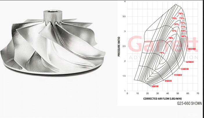
Chargers

Where is the vacuum modulator on a 1995 Chevy Silverado?

If your speaking of the vacuum modulator for the transmission, they no longer use them on the transmissions with overdrive and electronics. The powerglide, turbo 350 and turbo 400 used to use them.

Is a 2006 Dodge Magnum rt a turbo?

Where can you find a vacuum hose diagram for a 1987 Toyota Supra turbo?

I've Been Trying To Find This One For Weeks, Hope This Is What You Want. Just Highlight And Paste. opc.mr2oc.com/online_parts_catalog/1992_toyota_Vacuum_diagrams.pdf Regards M. R.

What is the vac pump on a Nissan 300ZX?

Answer Because of differences in the vacuum characteristics of a turbo and non-turbo 300ZX the turbo models (Z31 seriers anyway) have a vacuum pump added under the front bumper that comes on when sufficient vacuum is not available from the engine for only the following..water solenoid for heater, ac/heater controls, cruise control.

What is the firing order diagram on rs turbo?

Firing order on a ford escortfiesta rs turbo is 1342

Where are the vacuum lines located on a 1990 Nissan 300zx non-turbo?

V8 Single Turbo Diagram

You can find complete diagrams at http://www.CarGurus.com

Where can you get a complete wiring diagram for a 1985 Nissan 300ZX non-turbo?

try ebay, search 1985 300zx for the Nissan Service Manual, I have the 1986 manual , it contains the wiring diagram

I have an 1985 Dodge Daytona Turbo just had the engine rebuilt but am having an antifreeze leak and cannot figure out where it is coming from seems to be coming from above the valve covers any ideas?

Leaking coolant can be from many areas. On the 2.2 Turbo used in your Daytona, there isn't anything above the valve cover, but it could be leaking from the head/block mating surface, due to a blown headgasket or a warped cylinder head. Also the turbo vehicles have coolant feed and drain lines going to and from the turbo, checkout the connections on the turbo for leaks and also on the thermostat housing and the rear… Read More

Can you install a turbo into a 2008 dodge charger?

Both a Turbo and a Supercharger are relatively easy to install on the Chargers.

Does the dodge ram 1500 sport have a turbo?

What is the turbo on a 2006 dodge cummins?

Can you put a 1991 Dodge spirit turbo engine in a 1992 Dodge colt?

What are the release dates for Horsepower TV - 2006 Twin Turbo Dodge Challenger?

Horsepower TV - 2006 Twin Turbo Dodge Challenger was released on: USA: April 2010

Is there a non turbocharged dodge stealth?

Yes, there was the plain 3.0L, the 3.0L turbo, and the turbo all wheel drive.

Does the vacuum Modulator on the turbo 350 need to be hooked straight to manifold vacuum. Or can you use any vacuum port on the carb.?

It must be connected to a full-time vacuum source such as the intake manifold.

Can you Show me the diagram of a Mercedes turbo 300D vacuum connections?

Try http://www.mercedesshop.com/shopforum/showthread.php?t=105297 http://www.mercedesdismantlers.com/AutomaticTransmissionInformation.html http://ericandkat.com/mercedes/W123VacDoorLockDiag.doc http://www.peterschmid.com/vacuum/1980/617_950.jpg. Aws certified solutions architect pdf download free. http://www.performanceproducts4benz.com/Drawings.aspx?bmid=132 http://boostnbenz.1baddsm.com/DIY/Vacuum/ (Careful, some of these links are to www.ultrahot.com, and don't work)
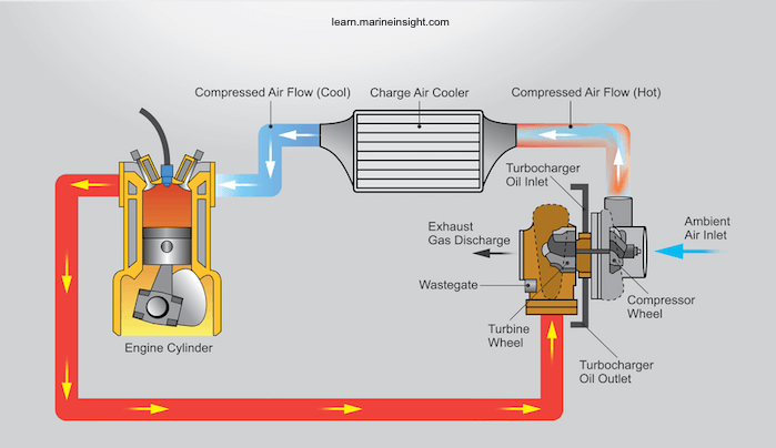
How to turbo a car cheap

Firing order on 4.9 Pontiac turbo?

printable diagram for firing order for 1980 trans am turbo 301 4.9 engine

What does hg stand for in a turbo meter?

A measurement of vacuum/pressure as in inches of mercury.

How do you check a Turbo a 1998 Dodge Ram 3500 5.9 Diesel?

How To Install A Twin Turbo

The best way to check your 1989 Dodge Ram 3500 5.9 liter diesel engine turbo is with a diagnostic tester. The diagnostic tester can tell you several things about the functioning of the Turbo.

What is trouble code P0299 on a dodge sprinter?

Where is wastegate on 2004 dodge 2500?

Will a 350 turbo swap out with a 700R4?

yes but the 350 turbo like the 400 turbo are vacuum run so you will need to tie into a vacuum line i put a turbo hydromatic 400 in my 1990 silverado that originally had a 700r4 it sucks not having overdrive but it will work also the output shaft is bigger so i needed a compatible transfer case in a 2wd this may not be a problem

How much power does a dodge stealth have?

225 hp for the es model (non turbo) 300 for the AWD twin turbo

Twin Turbo Installation Diagram

Can you put a turbo in a 2008 dodge charger?

Yes, you can put a turbo and a supercharger on the chargers. wear would i go to find out how

How do you change your 1993 dodge stealth sohc non turbo to a turbo?

a lot of time and money, or a mechanic is handy too